Technology
Tubular motor garage door controller based around PIC16f193x series With radio Tx/Rx
1. Introduction
1.1 This project has become a finished product, for one reason or another.
1.2 It is not here, on the web, so that a reader may build it for himself; I don't expect somebody to come here looking for a DIY project. Although, I am open to enquiries about the provision of PCB, and full firmware.
1.2.1 Rather, it is here as a bit of a showcase product; something which I have made 'full stack'; something which works perfectly; - finished in every detail for general and CE compliant use.
1.3 Why it is not therefore on general sale as a product in the market.. that is another story.
1.4 Below are:
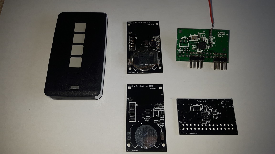
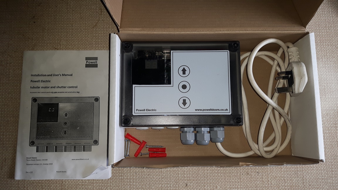
1.4.1 Photographs of the finished product
1.4.2 Firmware
1.4.3 schematic
1.4.4 PCB and gerber files
1.4.5 Bill of materials
1.4.6 Users manual
1.4.7 Notes on peripheral devices
1.5 I should give a brief description of what this is, provide the materials, and nothing more. Honestly, I can't bring myself to sell the farm for the sake of filling up a web page. All details of the product are to be found in the Users Manual (below). If you examine the code, you will find how it all works as per that manual.
1.5.1 If you have any enquiries about this product, build, or to make orders for parts of completed item, you are welcome to contact me at jason@powelldoors.co.uk.
1.5.2 The only thing not included in the release available here is the code for the handsets, and their Schematic / PCB / Gerber files. BOM list is available her, however.
1.5.3 Thank you.
2 Firmware
Download the C 1939 Central controller Source files
Download the C LF1936 Receiver controller Source files
3 Schematics
Download the main controller board schematic
Download the receiver board schematic
Download the transmitter board schematic
4 PCB and Gerber files
Download the main controller board pcb view
Download the receiver board pcb view
Download the transmitter board pcb view
Contact me for Gerber files
5 Bill of Materials
Download the main controller enclosure bom
Download the main controller pcb bom
Download the receiver card pcb bom
Download the handset bom
Download the handset pcb bom
6 Users Manual
Download the Users Manual
7 Notes on peripheral devices
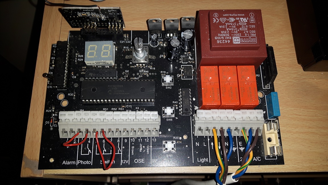
7.1 The main control board, shown below, should not be put into the field on a working door
unless provided with a door pressure / crushing safety sensor.
7.2 The last photograph below shows a hard wired helical cable attached safety sensor device
which I manufactured. The Infra Red decoding takes place on the board and inside the clear enclosure
shown. Concealed IR sender and receiver are not visible, but inside the EPDM weatherseal. See
project elsewhere in the Technology section of this site.
7.3 A wireless sensor (sans helical cable), using a 3.6v battery, is also available (see this site).
8 Product photographs


9. Copyright, Jason Powell, March 2020
Design Jason Powell, 2020.