Technology
5 UART / EUART Demonstration: PIC to PIC / PIC to Terminal Console
1. Introduction
1.1 This project is simply a demonstration.
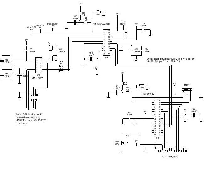
1.2 Here, a PIC24FJ64GB002 is hooked up with UART connection to a terminal console on a Personal Computer (PC); the communication flow is two-way, using the hardware handshake (although PuTTY console does not seem to need it).
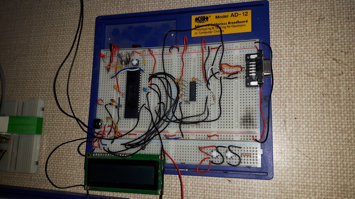
1.3 At the same time, the PIC24FJ also outputs via a second UART connection to a PIC16F1939. The PIC16F receives the serial communication and outputs what has been received by it to an LCD screen. The PIC16F EUART module only requires two wires, and uses interrupts to handle its internal buffer. All of these communications are at a basic level, but functional.
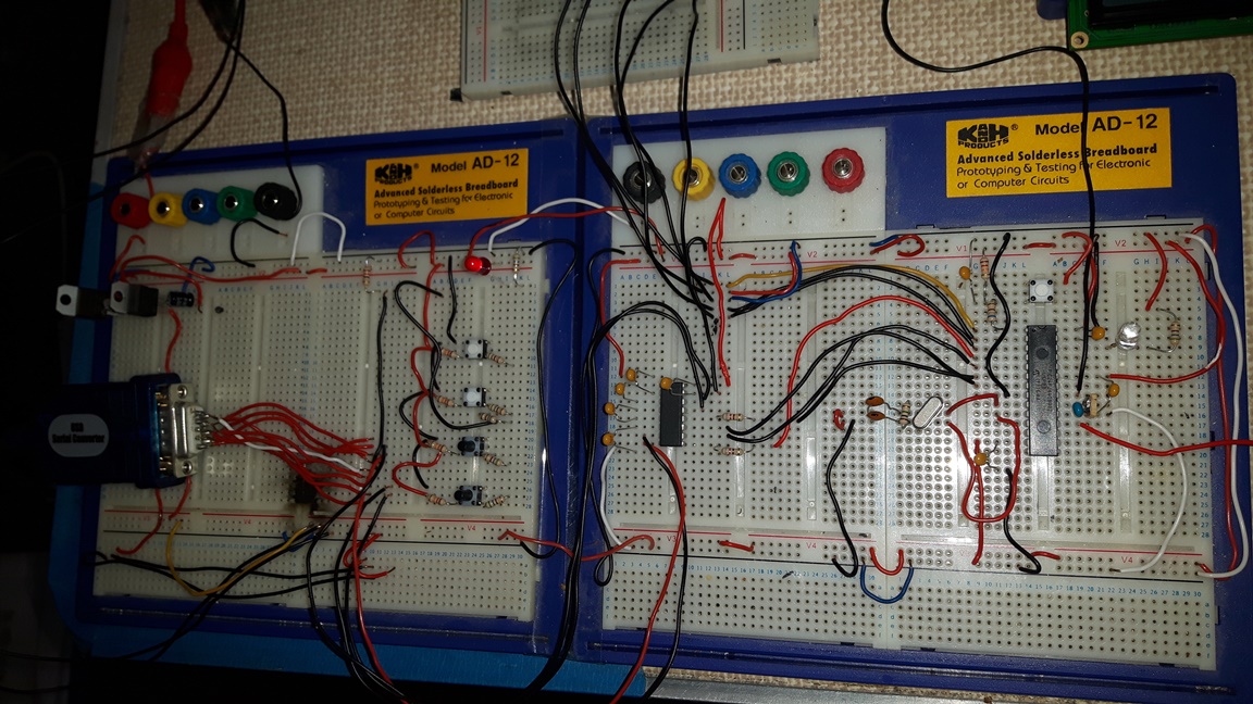
1.4 Firmware, schematics, a cheap set of photographs, and a bit of explanation of the serial UART / EUART processes and set up
are to be found below.

2 What this does
2.1 Using the schematic (the photos, if you like) as a guide, attach the PIC24FJ64GB002 circuit to a PC. Do this with a DB9 female socket on your breadboard. Then, a Serial cable to the PC (if the PC does not have a DB9 input, use a USB Serial Converter cable).
2.2 Open up or download a serial terminal window such as PuTTY. Set the PuTTY at 9600 baud, 1 stop bit, 8 bit data, no parity, and RTS/CTS hardware handshake.
2.3 While PuTTY has focus on your PC typing into the keyboard will send the keystrokes to the PIC24FJ device; when the key strokes are received, the PIC24FJ will respond by sending a string to the terminal window, thus displaying text.
2.3.1 The firmware has been so designed that strings are sent, rather than individual characters, which means that backspace, arrow keys, and the carriage return keys can also be used while the string is still only residing in the Buffer (declared as an array in the main.c file).
2.3.2 In addition, the firmware includes the printf() functions, and our own proprietary string manipulation functions using pointers, so that the status of PIC24FJ registers can be displayed, or other useful debugging information. Otherwise, as a demonstration only, this code, schematic, and photos are pretty useless.
2.4 Since the PIC24FJ has two UART modules, I took the opportunity to use the other one, the UART2, to communicate with a 5 Volt device from the
mid-range PIC16F series. UART2 on the PIC24 simply
hooks up to the PIC16 EUART directly. For its part, the PIC16 uses EUART, and interrupts are enabled. In this set up, here, the
PIC16 does not transmit, but simply accepts the string which was created by the PIC24 before the string line termination character / carriage return, then prints it to the LCD screen.
3 Notes on the UART, PIC24FJ64GB002
3.1 Baud and Register settings
Internal crystal used, for simplicity.
4MHz clock freq. (FOSC)
2MHz (FCY) = FOSC / 2
BRGH set to 1; for high speed processing
See DS39940D, PIC24FJ64GB004 Family datasheet, page 190 (2010 version).
Baud rate for UxBRG calculation: UxBRG = ((FCY / Baud Rate) / 4) -1
((2,000,000 / 9600) / 4)-1 = BRG of 51 decimal, or 0x33 hexadecimal.
U1BRG and U2BRG therefore follow the datasheet with a value of hex 33.
Data Bits = 8; Parity = None; Stop Bits = 1;
U2MODE = (0x8000); -- STSEL 1; IREN disabled; PDSEL 8N; UARTEN disabled; RTSMD disabled; USIDL disabled; WAKE disabled; ABAUD disabled; LPBACK disabled; BRGH enabled; RXINV disabled; UEN TX_RX;
U2STA = 0x00; -- UTXISEL0 TX_ONE_CHAR; UTXINV disabled; OERR NO_ERROR_cleared; URXISEL RX_ONE_CHAR; UTXBRK COMPLETED; UTXEN disabled; ADDEN disabled;
U2BRG = 0x33; -- BaudRate = 9600; Frequency = 2000000 Hz; BRG 51;
U2MODEbits.UARTEN = 1; U2STAbits.UTXEN = 1; -- enabling UART ON bit
The hardware handshake is not respected by the PuTTY console, and the transmission and reception occur regardless. They can be used where the second UART device also includes such Ready to Send and Clear to Send lines.
The UART is interrupt based, and sends / receives so long as there are no other higher priority interrupts taking place. Interrupts
do not need to be handled by firmware, and flags are cleared by automatically, being simply status flags.
4 Notes on the EUART, PIC16F1939
4.1 Baud Generation:
FOSC is 500,000 using the internal crystal, FOSC = INTOSC
Calculation, in asynchronous mode, for 16-bit BRG value is:
FOSC / (4*(9600+1))
((FOSC / Desired baud rate) / 4)-1
So: 500,000 / (4*9601) = 12 decimal, or 0x0C hexadecimal
(See Datasheet, PIC16(L)F1938/9, page 299. 2011-13 version
SPBRGL = 0x0C; -- SPBRGL 12;
SPBRGH = 0x00; -- SPBRGH 0;
BAUDCON = 0x08; -- ABDOVF no_overflow; SCKP Non-Inverted; BRG16 16bit_generator; WUE disabled; ABDEN disabled;
RCSTA = 0x90; -- SPEN enabled; RX9 8-bit; CREN enabled; ADDEN disabled; SREN disabled;
TXSTA = 0x24; -- TX9 8-bit; TX9D 0; SENDB sync_break_complete; TXEN enabled; SYNC asynchronous; BRGH hi_speed; CSRC slave;
4.1.1 As before, enable interrupts, watch interrupt flags, and buffer contents will move in and out automatically from the registers assigned for the EUART.
4.2 Additional Notes:
4.2.1 If there is any capacitance on the lines, and you can’t seem to get the output to work on the terminal window without putting a finger near to the wires,
then it is because your TX / RX lines are mixed up; swap them around. If it takes around 2 days to figure this out, then you have done about as well as me. But that is in the nature of this game.
5 Firmware and Schematic
Download Firmware for the PIC24FJ64GB002
Download Firmware for the PIC16F1939
6 Copyright, Jason Powell, March 2020
Design Jason Powell, 2020.