Technology
6 The SPI module on the Microchip PIC24FJ series
1. Introduction
1.1 The project below is a demonstration only.
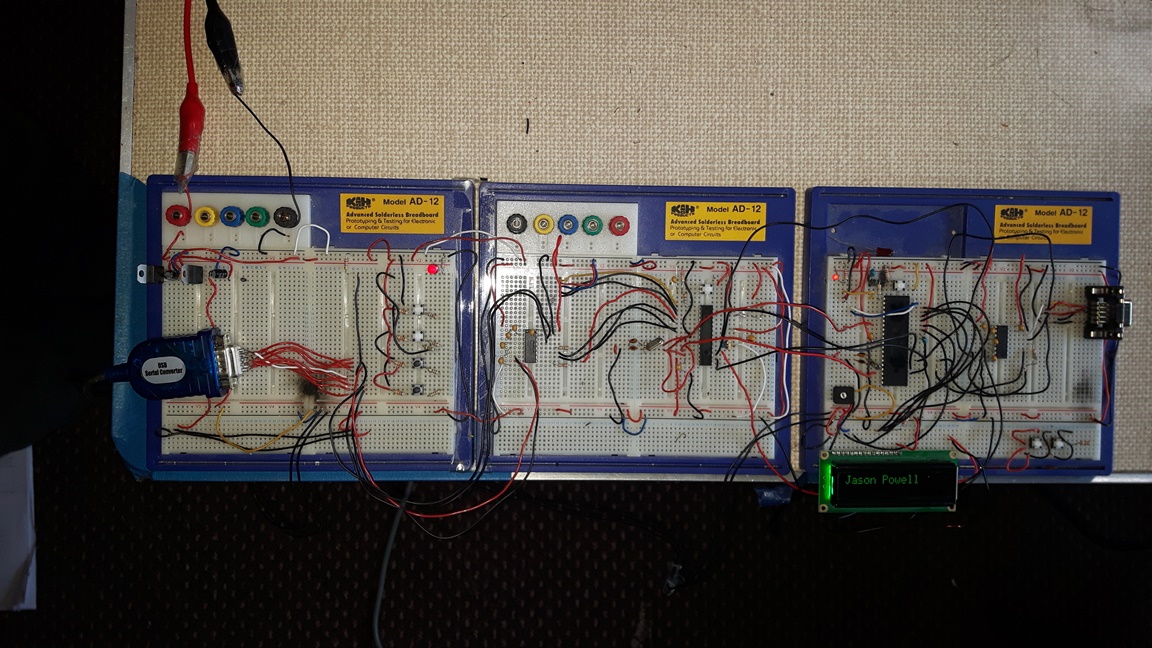
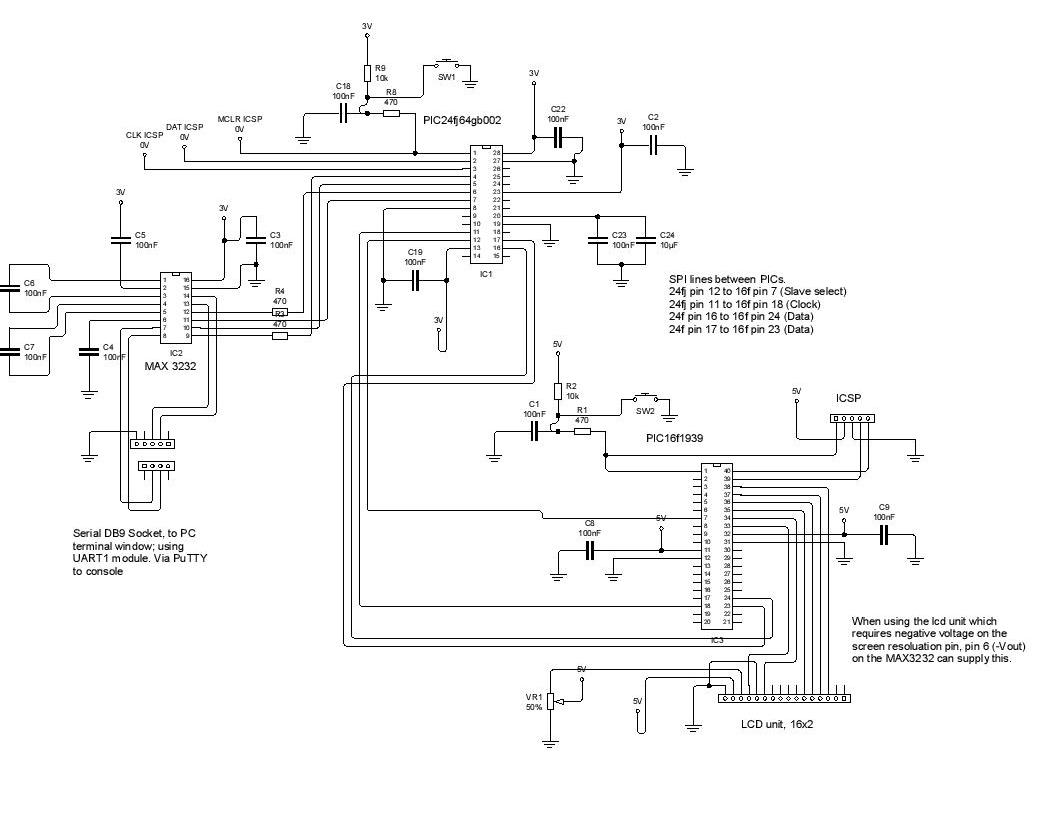
1.2 I show how to connect a PIC24FJ64GB002, which has a keyboard and PC console connection (via UART), to a PIC16F1939, which has an LCD display output.
1.3 When keystrokes are made at the PC, the UART-based *s=getch() function on the PIC24 picks up the keystroke byte of information; it then sends this byte via the putch( *s) function to the console screen, which converts it into an on screen character / letter.
1.3.1 In effect, we have a PIC24 UART connection to the console of a PC; the connection is going both ways, and the PIC24 is in this instance the means of showing characters on the console screen.
1.3.2 See project ‘5 UART / EUART Demonstration’, above for more information.
1.4 Working from this basis, we have added to the PIC24 an SPI connection to a PIC16.
1.4.1 When a keystroke is made on the PC’s keyboard, the byte of information is received by the PIC24, and transferred with the spi1_exchangeBlock(s, 1) function to the PIC16.
1.4.2 This uses the SPI module, enabled on both PICs.
1.4.3 The PIC16 then takes that byte and prints it to the LCD screen.
1.5 That, in summary , is that the present project does. It demonstrates the SPI communication from a master device (PIC24) to a slave (PIC16), and I include the various screens as proofs or debugging tools to show that the process is successfully working.
1.5.1 Why anyone would want a keyboard writing to an LCD screen in any other situation, I can’t guess.

2. Notes on setting up the SPI
2.1 To make the SPI work, you need a couple of PICs which are set up for programming.
2.1.1 Get them flashing an led or something, on both sides.
2.1.2 Set up the various SPI control registers, following the datasheets for each.
2.1.3 Choose which one should be the master, which the slave, and set the registers for each accordingly.
2.1.4 Pay attention to the clock polarity settings, or the ‘spi mode’; the CKE and CKP bits for each device must match.
2.1.5 There is no baud setting, since the master will provide the clock.
2.1.6 Ensure TRIS ad A/D registers are suitable; at the slave end, the SS and Clock pins will be input; and there is no analog here.
2.1.7 And turn on interrupts at the slave side, since we will need to get an interrupt at the slave end in order to retrieve the byte which is to be sent.
2.1.8 Use an oscilloscope to check that the clock starts up for every transmission; check that the SS line goes low; and that data is being sent from the master SDO pin.
2.1.9 Ensure the SDO pin is connected to the SDI on the other device, and vice versa.
2.2 If there are other functions going on at the same time, or you are using an already set up board with processes and pins already in use, then make absolutely sure that there is no kind of conflict, or overlap of pin usage (an obvious mistake, I know).
2.3 If you are getting stuck, why not use the MPLABX MCC code configurator? If you get really stuck with a project like this, such as setting up a new kind of process, as a
beginner: strip the device down to essentials, and write the code from scratch (using the mcc, perhaps), and make the device do only that simple task which you are
focusing on. At a later time, when the device is working as expected on the simple task, build the code and the hardware back up with the other processes, deconflicting them as you go.

3. The following shows the register set up for the PIC16.
3.1 Set up
SSPSTAT = 0x00;
SSPCON1 = 0b00000100;
SSPADD = 0x00;
TRISCbits.TRISC3 = 1; // the Slave select pin
SSPCON1bits.SSPEN = 1;
INTCONbits.GIE = 1; // enable interrupts
INTCONbits.PEIE = 1;
PIE1bits.SSPIE =1;
PIE2bits.BCLIE =1;
3.2 And the interrupt routine:
if(INTCONbits.PEIE == 1)
{
if(PIE2bits.BCLIE == 1 && PIR2bits.BCLIF == 1)
{
SPI_ReadByte();
PIR2bits.BCLIF = 0;
if_flag = 1;
}
else if(PIE1bits.SSPIE == 1 && PIR1bits.SSPIF == 1)
{
SPI_ReadByte();
PIR1bits.SSPIF = 0;
if_flag = 1;
}
}
3.3 And the receive routine:
uint8_t SPI_ReadByte(void)
{
return SSPBUF;
}
So, the main.c while loop will have the the SSPBUF to play with after an interrupt; the interrupt
occurs when there is activity in the receive buffer.
4. The following shows the register set up for the PIC24.
4.1 Set up
TCSEE = 0; // ss pin in output
CSEE = 1; // start high, and clear to low when transmitting
SPI1CON1 = 0b0000000000100000;
SPI1STAT = 0b1000000000000000;
4.2 The send / TX command in the main while loop
CSEE = 0; // clear the ss pin, active low
spi1_exchangeBlock(s, 1);
CSEE = 1;
4.3 The transmit routine
void spi1_exchangeBlock(void *block, size_t blockSize)
{
uint8_t *data = block;
while(blockSize--)
{
*data = spi1_exchangeByte(*data );
data++;
}
}
5. Schematic
Download Schematic
6. Firmware
Download Firmware for the PIC24FJ64GB002
Download Firmware for the PIC16F1939
7 Copyright, Jason Powell, March 2020
Design Jason Powell, 2020.