Technology
7 Radio Transceiver MRF89XAM8A with PIC24FJ64GB002
1. Introduction
1.1 The project below is a demonstration only.
1.2 The MRF89X module used here is the MRF89XAM8A, which the is version meant for use at 868MHz.
1.3 The module is ready to use with communication via SPI. Its uses appear to include Wireless internet applications, although I have not here demonstrated it in that function.
1.4 The module datasheet, below, tells more about the various modes it can be used in.
1.5 Microchip also supply a Radio Driver software which can be uploaded to their Explorer 16, using the PIC24FJ128GA010. I have taken that code and made some alterations to run it on the PIC24FJ64GB002, which has the advantage of coming in a DIP package.
1.6 The Radio Driver set of files, particularly the Radiodriver.c file, allows you to configure the module after ever reset. Having cut it down a bit, in part as an example of what you can do with the original c files, I have now restricted the functionality to:
1.6.1 On the TX side, a simple transmission of a predifined HEX packet.
1.6.2 On the RX side, a choice of receiving and displaying the data in verbose mode, packet count, or summary.
1.7 To set up the module, you need to have a UART connection via a MAX3232 chip, and this needs to be on the RX and TX.
1.8 It can be demonstrated to work by setting up both modules, one as RX and one as TX. Then viewing the transmissions with a Console from the UART serial DB9 socket. Then, viewing the received information via an LCD screen.
1.9 As set up here, with the firmware, the LCD will only display the summary information.
1.9.1 The LCD will display the summary as the number of packets received - in a binary value; your LCD will then display this binary numerical value as an ASCII character.
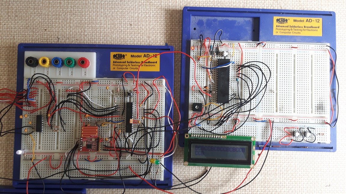
1.9.2 For instance, if the receiver has a value of 66 packets received, then the ASCII character will show the character 'B'. Or, for 67 packets received, the character 'C'.
1.10 This confirms that, when the TX Console is showing 66 packets sent, then the RX side should print a 'B' character to the LCD screen.
1.11 Note, anything more complex than this requires some kind of transceiver system where each packet is sent only when the receiver
packet has been received and processed. I have not gone into this level of synchronous development or 'ping pong' of the data acknowledgement.
2. Photographs
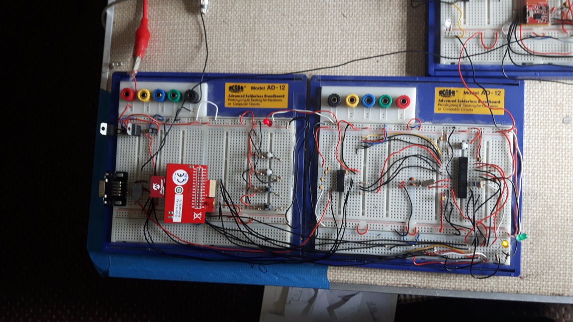
2.1 TX set up
2.2 It will be noticed that on this side I have used the PicTail variant of the MRF89X module, with the wires attached to specific pins of the
module.

2.2 RX set up

3. Notes on Firmware
3.1 The code was successfully ported to the PIC24FJ64GB002 only after I had removed the complication of the external crystal. Therefore, the SPI connection is running from the internal FOSC. This has also impacted on the Baud rate, which should be set in the Console at 9600.
3.2 Note that I have also cut down the Radio Driver set up considerably, and an original version of the RadioDriver.c file should be used if you want to return to the full functionality. File attached, below.
3.3 Finally, note that transmission and reception is limited in my files to 868MHz, 20kbps, at FSK modulation.
Download the original Radio Driver firmware
4. Schematics
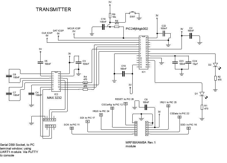
4.1 There are three schematic sheets to view:
4.1.1 The TX device

4.1.2 The RX device

4.1.3 The RX device LCD chip and connections

4.2 Each can be downloaded below.
TX PIC 24f to MRF
5. Firmware
6. Datasheets
PIC16F1939 Datasheet
PIC24FJ64GB002 Datasheet
MRF89XAM8A Transceiver Datasheet
7 Copyright, Jason Powell, March 2020
Design Jason Powell, 2020.