Technology
Simple PIC to PIC I2C communications and LCD
1. Introduction
1.1 The project below is a demonstration only.
1.2 This project demonstrates the MSSP module on the PIC16F1939.
1.3 This pair will run continuously incrementing, sending decimal values 65 through up to 80, which are asci characters capital A to capital 0. The lcd displays these, with 500ms delay between each sending / increment.
1.4 This therefore demonstrates a simple master send on the PIC16F and a receive on the same model of chip, which displays the result to an lcd.
2. Set up
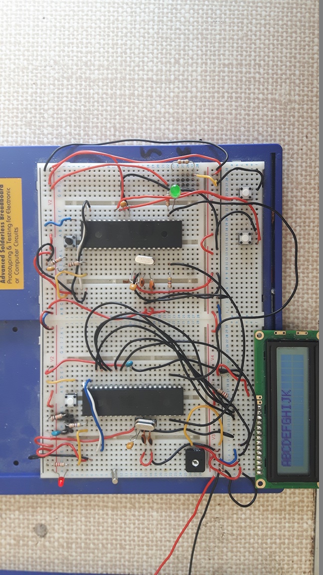
2.1 Schematic and firmware are to be found below.
2.2 Slave settings and receive routine (but use the complete code in the downloads, below, to get this working).
I2C_Slave_Init(0x40); // Initiate I2C Slave With Address = 0x40
while(1)
{
if(flag1 == 1 && RX_Data == 65)
{
Lcd_Clear();
Lcd_Set_Cursor(1,1);
Lcd_Write_Char(RX_Data);
flag1 = 0;
}
if(flag1 == 1 && RX_Data > 65)
{
Lcd_Write_Char(RX_Data);
flag1 = 0;
}
}
}
//----------------[ END OF MAIN ]-------------------
//==================================================
void __interrupt() ISR(void)
{
if(SSPIF)
{
flag1 = 1;
if(!R_nW) // Slave Write (Receive)
{
char Dummy = SSPBUF; // Dummy Read
CKP = 1; // Release The SCL Clock Line
while(!BF); // Wait Until Completion
RX_Data = SSPBUF; // Read The Buffer Data
}
CKP = 1; // Release The SCL Clock Line
SSPIF = 0; // Clear The Interrupt Flag
}
}
//---------------[ I2C Routines ]-------------------
void I2C_Slave_Init(unsigned char Address)
{
//---[ Configures The I2C In Slave Mode]---
SSPADD = Address; // Set The I2C Slave Device Address
SSPSTAT = 0x80;
SSPCON = 0x36;
SSPCON2 = 0x01;
TRISC3 = 1; // SCL Set To Input
TRISC4 = 1; // SDA Set To Input
GIE = 1; // Enable Interrupts
PEIE = 1;
SSPIF = 0;
SSPIE = 1;
}

2.3 Master settings and Tx routine
void main()
{
TRISB = 0xFF;
TRISD = 0x00;
PORTD = 0x00;
unsigned char i=65;
I2C_Master_Init();
while(1)
{
char x;
I2C_Start(); // try start here
for(x=0;x<=15;x++)
{
I2C_Write(0x40); // I2C Slave Device Address + Write
I2C_Write(i++); // The Data To Be Sent
}
I2C_Stop();//stop here
i = 65;
__delay_ms(1000);
LATDbits.LATD3 = ~LATDbits.LATD3; // Toggle LED Each Time A Byte Is Sent!
}
}
3. Notes on Firmware
3.1 Slave reception is interrupt based, and interrupt flag is set on 9th falling edge of master clock
3.2 Most of I2C is done by the I2C register, so send and receive are easy.
3.3 An oscilloscope is essential for debugging I2C
3.3.1 E.g, if the clock gets stuck, or to see it transmitting
3.3.2 See photograph below for typical use of oscilloscope here. A chief use of the scope is to visually check whether the clock starts up when a transmission is being made.
3.3.3 And, whether the clock lines stays low, or goes high again after the transmission.
3.4 Also, in my set up, I had to pay attention to the config settings.
3.4.1 I wanted to use the 8MHz clock external crystal. Tried without it. Eventually messed about until I got something, and, typically, worked out the frequency and Baud settings, etc., only once I had it actually working.
3.5 The I2C clock frequency is calculated as follows:
3.5.1 See data sheet for examples of the BRG setting, which must be loaded into the SPPADD register, (see page 281 of the datasheet for the PIC16F1939).
3.5.2 Example from the datasheet:
Fosc: 4MHz
Fcy: 1MHz
BRG: 9 (0x09) hex
Fclock I2C clock frequency: 100,000 Herz (advised max for this chip)
The calculation is as follows:
(((FOSC / 4) / required Baud rate) – 1)
(((8,000,000/4)/100,000)-1) = 19
Or, 0x13 hex
See photo which shows a crystal cycle (FOSC) every 0.000000125 (0.125uS), or 8MHz.
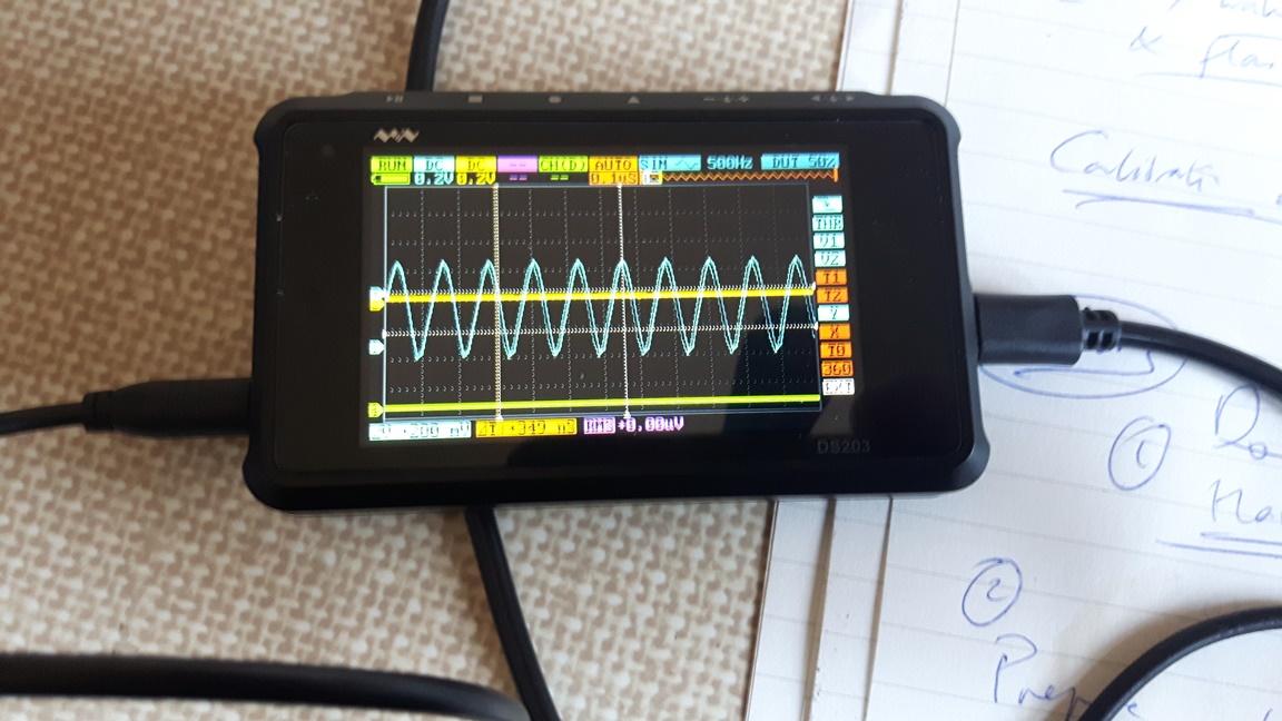
3.6 This is from an inexpensive digital storage oscilloscope from Miniware, model DS203.
3.7 The image shows that the external crystal is active, and running at 8MHz.
3.7.1 The graticules on the display are set 0.1uS intervals. The scope shows that the external crystal makes a full cycle
every 0.125 uS, which is 8,000,000 times per second (8 MHz).
4. Schematics
4.1 The connection of the PIC16F1939 to PIC16F1939 can be downloaded here.
PIC16F1939 pair schematic with lcd
5. Firmware
Download Firmware for both sides
6. Datasheets
PIC16(L)F1938/9 datasheet - DS40001574C
7. End
Design Jason Powell, 2020.